Fertilizer Mineral Grinding Solutions
Fertilizer Mineral Grinding Plant Layout and Equipment Selection
2026-10-19 10:53:47
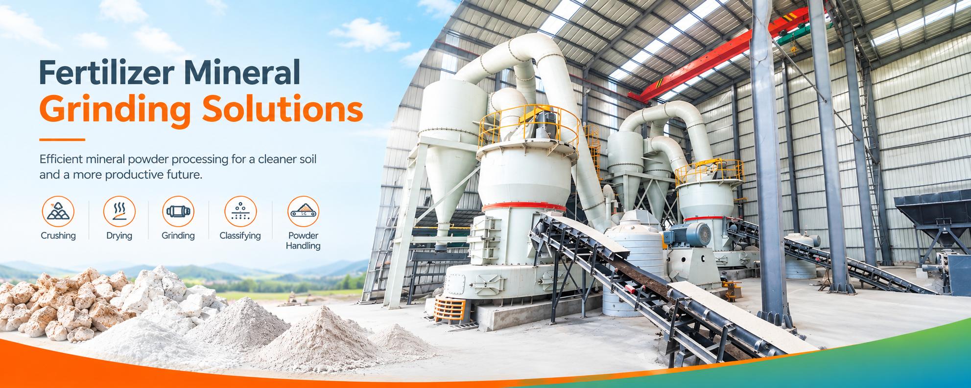
A fertilizer mineral grinding plant should be laid out around the movement of material, the required powder specification, and access for operation and maintenance. Select the grinding equipment only after defining the mineral feed, finished fineness, moisture range, production rate, and downstream delivery requirements.
The objective is not to fit the largest mill into the smallest building. It is to create a coordinated production system in which receiving, feed preparation, grinding, collection, storage, and dispatch can operate without avoidable bottlenecks.
Begin with a Design Basis, Not an Equipment Drawing
Before positioning machinery, prepare a short design-basis document. This gives the equipment supplier, civil designer, electrical team, and downstream process owner the same set of requirements.
| Design Input | Information Required | Layout or Selection Consequence |
|---|---|---|
| Raw material | Mineral type, source, composition, impurities, and variability. | Determines material qualification, segregation, and testing requirements. |
| Feed condition | Maximum lump size, size distribution, moisture range, and handling behavior. | Determines crushing, storage, feeding, and potential drying arrangements. |
| Finished powder | Particle size distribution, moisture, and chemical acceptance criteria. | Defines the grinding and classification duty. |
| Production schedule | Required hourly output, operating hours, and product changeovers. | Influences equipment sizing, buffer capacity, and maintenance planning. |
| Delivery interface | Bulk dispatch, bagging, or direct transfer to another process. | Determines finished storage and loading equipment. |
| Site conditions | Available land, building restrictions, ground conditions, utilities, and access. | Sets the practical boundaries for the general arrangement. |
Separate confirmed information from assumptions. Where moisture, grindability, or product requirements remain uncertain, identify the testing needed before equipment commitments are made.
Organize the Plant into Five Functional Zones
A clear zoning arrangement makes material movement easier to understand and helps prevent vehicle traffic, maintenance work, and production activities from interfering with one another.
1. Receiving and Raw Material Storage
Position receiving where trucks or loaders can unload without crossing finished product loading routes unnecessarily. Provide space for inspection, sampling, and temporary isolation of nonconforming deliveries.
If several minerals will be processed, plan separate storage bays or bins where mixing would affect product quality. Consider weather protection and drainage before relying on downstream drying to manage avoidable water entry.
2. Crushing, Conditioning, and Feed Buffering
Locate the crushing stage, where needed, so that material can reach the mill feed bin through a practical conveyor or elevator route. Include foreign-object removal and screening where the selected process requires them.
The buffer bin should support stable feeding during normal upstream interruptions. Its usable capacity depends on reliable discharge, not simply its geometric volume.
3. Grinding and Classification
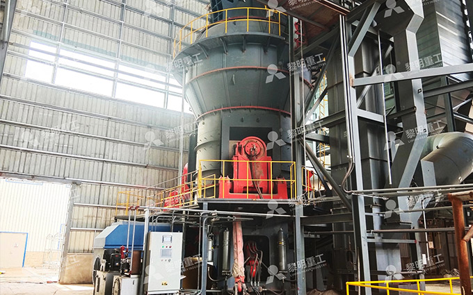
Position the main mill with adequate structural support, equipment access, and space for its associated classifier, ductwork, and service connections. Keep the grinding arrangement coordinated with the fan and collection system rather than locating each item independently.
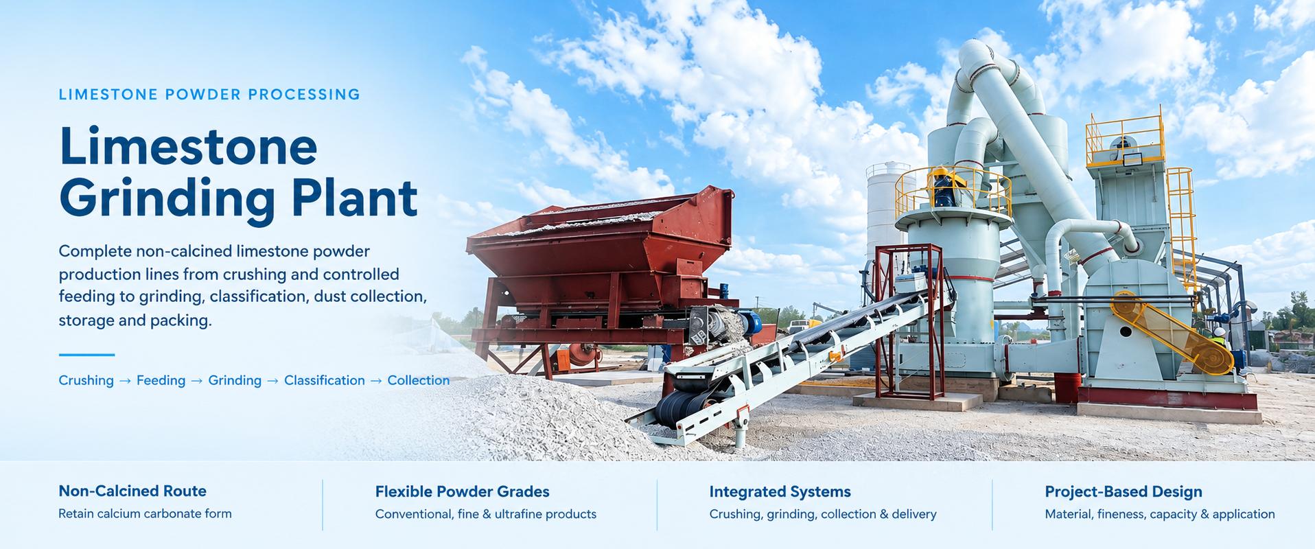
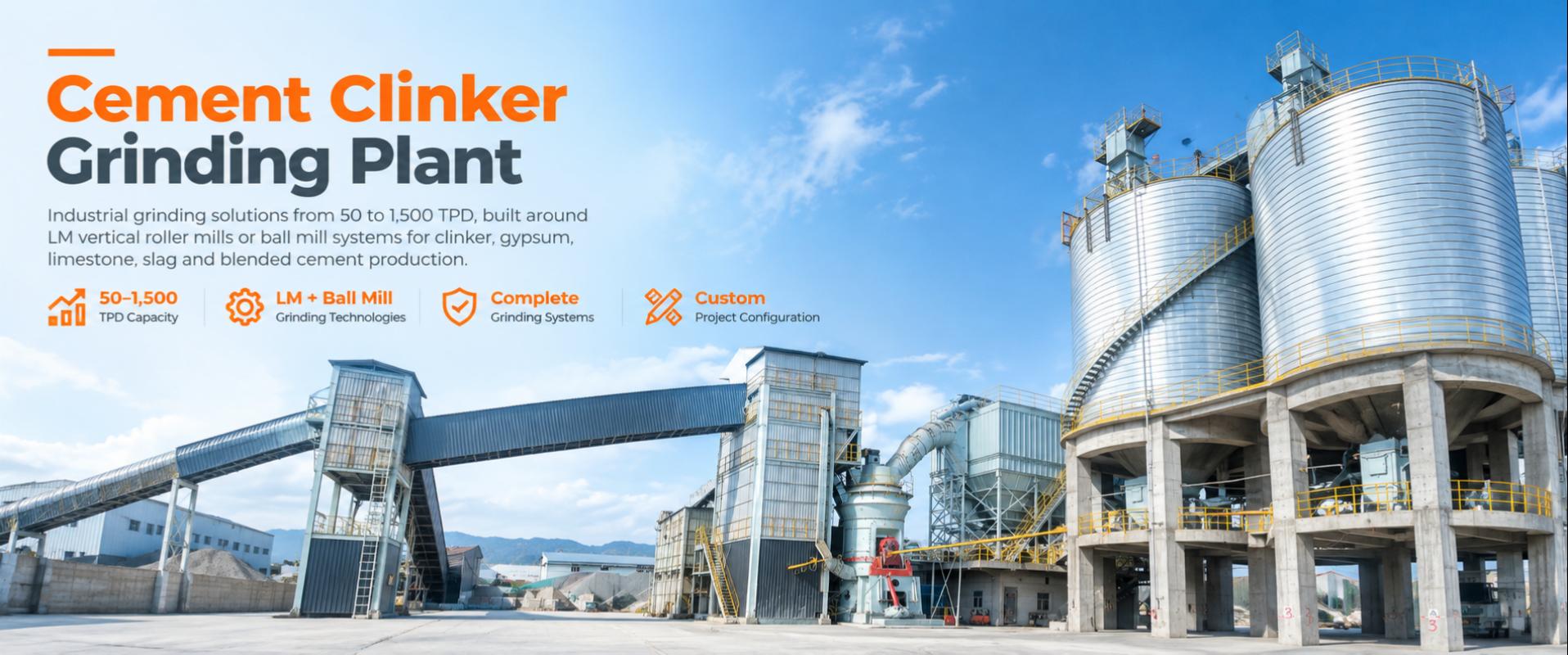
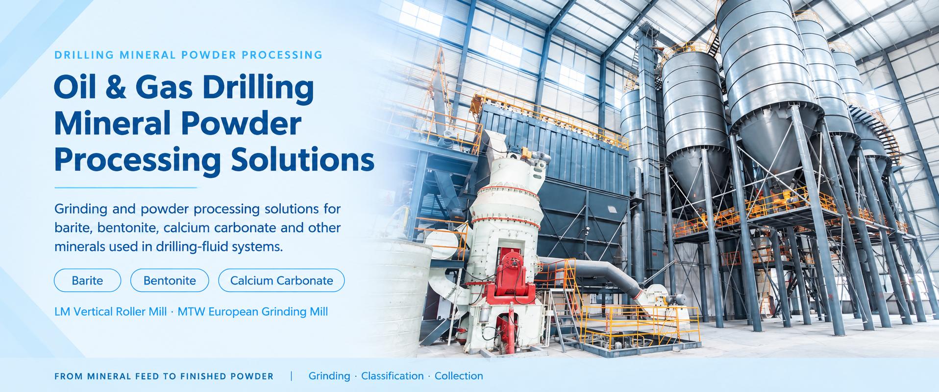
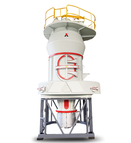
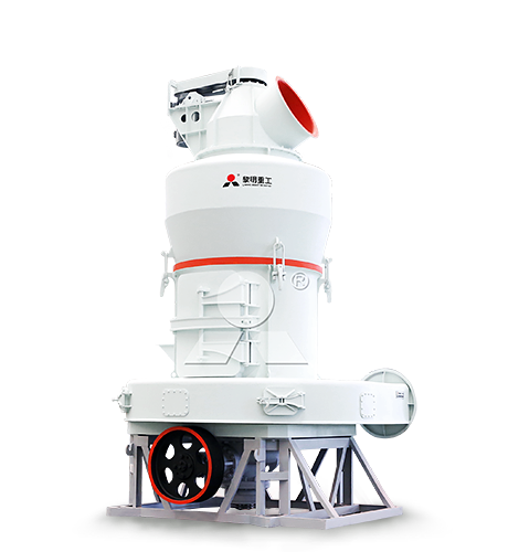
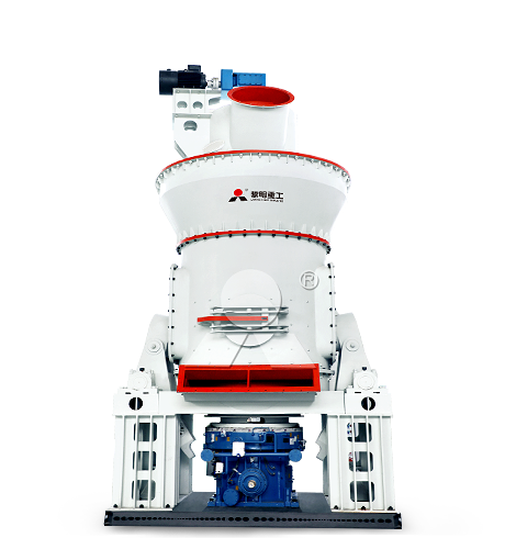
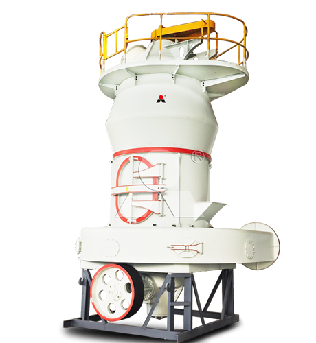
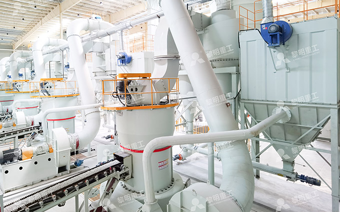
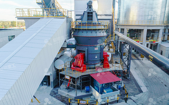
Liming Heavy Industry’s LM Vertical Roller Mill integrates drying, grinding, classification, and conveying, while the MTW European Trapezium Grinding Mill operates with a supporting separator, blower, feeding system, and powder collection equipment. These different arrangements should be reflected in the layout.
4. Powder Collection and Finished Storage
Allow a practical route from collection equipment to the finished silo or receiving process. Review collector discharge, conveying capacity, inspection access, and the space needed to service filter components.
For multiple products, define how accepted powder will remain segregated. Include transition material and cleaning requirements in the storage plan.
5. Packing, Loading, and Downstream Transfer
Place bagging and bulk loading where vehicles can approach, load, and leave safely. Provide suitable access for weighing, sampling, and product identification.
Where powder transfers directly to fertilizer manufacturing, agree on delivery rate, moisture, temperature, buffer capacity, and operating sequences with the receiving plant.
Select LM or MTW Around the Complete Production Duty
Both Liming Heavy Industry LM and MTW grinding systems can be evaluated for suitable nonmetallic mineral powder applications. The correct selection depends on the actual material and product specification—not simply a broad capacity category.
| Selection Question | LM Vertical Roller Mill Review | MTW European Trapezium Grinding Mill Review |
|---|---|---|
| How will the mineral be ground? | Evaluate the rotating grinding table, roller arrangement, and integrated classification system. | Evaluate the roller-and-ring grinding arrangement and associated separator. |
| Does the feed require drying? | Assess the proposed integrated drying duty against actual moisture and available heat. | Confirm permitted feed moisture and any required upstream conditioning or separately engineered drying. |
| What determines useful output? | Accepted powder at the specified fineness and moisture using representative feed. | Accepted powder at the same defined feed and product conditions. |
| What must the layout accommodate? | Mill structure, service connections, hydraulic maintenance access, collection equipment, and material transfer. | Mill, separator, blower, ductwork, collection equipment, feeding, and discharge arrangements. |
| What evidence supports selection? | Material testing and a configuration-specific performance proposal. | Material testing and a configuration-specific performance proposal. |
The LM system uses a grinding table and rollers, with qualified powder leaving through the airflow for collection. The MTW system grinds between rollers and a ring, returning coarse particles from the separator for further grinding.
Avoid treating advertised family-wide capacity ranges as project guarantees. Ask Liming Heavy Industry to state the feed conditions, product distribution, moisture duty, and equipment boundary behind the proposed output.
Apply Material-Specific Selection Checks
A fertilizer mineral plant may handle phosphate rock, limestone, dolomite, gypsum, or bentonite. Each requires its own assessment.
For phosphate rock, obtain the receiving process specification and evaluate representative ore grindability and abrasive impurities.
For limestone and dolomite, confirm whether fine grinding is necessary for the intended agricultural grade or formulation.
For gypsum, distinguish free-moisture removal from unwanted changes to the specified mineral condition.
For bentonite, assess wet-feed handling and the functional properties required after processing.
The MTW product guidance lists limestone, dolomite, gypsum, and bentonite among applicable materials, subject to stated feed conditions. That list does not replace material testing or establish identical performance across minerals.
Choose a Layout Strategy That Suits the Site
Predominantly Linear Arrangement
A linear arrangement can work where sufficient land is available and material can move progressively from receiving to dispatch. Review conveyor lengths, transfer points, traffic routes, and access between equipment groups.
Do not extend the line merely to avoid all elevation changes. Compare the complete conveying and maintenance implications.
Vertically Arranged Sections
A vertically arranged section may use gravity transfer between selected stages. Evaluate structural loads, building height, access platforms, lifting requirements, and the route for removing major components.
Reduced ground footprint does not necessarily mean lower construction cost or easier maintenance.
Connection to an Existing Fertilizer Plant
For an expansion, begin with a site survey and agreed tie-in points. Check existing structural capacity, utility availability, silo access, vehicle movement, and shutdown requirements before positioning new equipment.
Define which existing equipment can be retained and verify its capacity. An existing conveyor or collector should not be assumed suitable simply because it is already nearby.
Reserve Maintenance Space Before Optimizing Footprint
The most valuable layout allowance is often access.
Provide defined service areas for grinding components, classifier inspection, fan servicing, collector maintenance, and electrical equipment. Include lifting arrangements and a route for moving replacement parts from the delivery point to the machine.
The LM mill incorporates a hydraulic roller turning-out arrangement for maintenance. Its required movement and service envelope should be shown on the general arrangement drawing rather than left as unspecified empty space.
Use supplier-approved dimensions for these clearances. Generic spacing rules cannot establish the removal envelope for a particular mill, motor, gearbox, or filter assembly.
Size Storage Around Operating Scenarios
Storage should protect production from foreseeable interruptions without creating unnecessary inventory or difficult discharge conditions.
Review at least these scenarios:
Raw material delivery stops while grinding continues.
The crusher stops while the mill remains available.
The downstream fertilizer process stops while powder production continues.
Dispatch is delayed during otherwise normal production.
The plant changes from one product grade to another.
For each case, decide whether the plant will continue, reduce output, divert material, or stop. Use these decisions to establish buffer and finished storage requirements.
Check Utilities and Controls as Part of Equipment Selection
Prepare a coordinated utility schedule covering electrical loads, compressed air, drying heat where needed, and control requirements. Identify normal demand, starting requirements, and the equipment included in each total.
Develop operating sequences and interlocks with the supplier. Feeding should not continue into unavailable downstream equipment, and any heated system needs an agreed response to loss of material flow or abnormal conditions.
Also define the division of supply: instruments, cables, motor control equipment, local panels, central controls, installation, and commissioning. Missing scope can create delays even when the main machinery has been selected correctly.
Approve the Layout Through Practical Reviews
Before construction, review the general arrangement with operations, maintenance, civil, electrical, and downstream process teams.
Trace every material route from unloading to final dispatch.
Check each transfer point for capacity, inspection, and dust-control access.
Verify equipment foundations and structural loads using supplier data and site engineering.
Confirm maintenance envelopes and lifting routes.
Review vehicle movement, pedestrian access, and emergency arrangements.
Confirm utility routing and installation access.
Identify future expansion areas without obstructing the first-stage plant.
Finalize equipment procurement and civil work against coordinated, approved drawings—not an early concept sketch.
Information Needed for a Practical Plant Proposal
Provide Liming Heavy Industry with representative mineral samples or test reports, maximum feed size, moisture range, required particle size distribution, hourly output, operating schedule, and downstream application.
Include a dimensioned site plan, available building height, utility conditions, raw material delivery method, finished product dispatch method, and any existing equipment interfaces. These inputs allow LM and MTW configurations to be compared within a realistic plant arrangement, with supporting equipment and installation requirements clearly defined.