GGBS Grinding Plant
GGBS Grinding Plant: Equipment, Process Flow and Plant Layout
2026-09-10 10:59:44
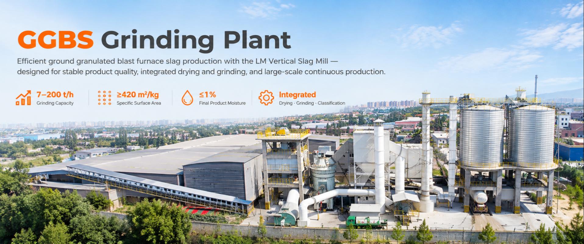
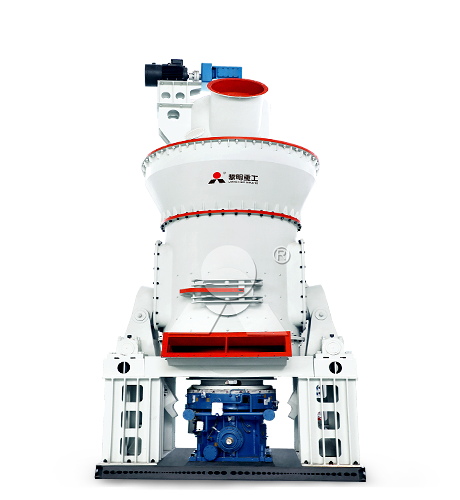
A GGBS grinding plant converts water-granulated blast-furnace slag into a controlled fine powder through receiving, preparation, drying, grinding, classification, collection, storage, and dispatch. A well-planned plant places the LM Vertical Slag Mill from Liming Heavy Industry at the center of the process, allowing wet slag drying, fine grinding, powder separation, and pneumatic conveying to operate as one coordinated system.
The most effective plant design starts with the material route, not with individual machines. Granulated slag is often wet, abrasive, and variable in moisture after storage. Therefore, feed handling, hot-gas supply, metal removal, mill capacity, dust collection, and finished-product logistics must be designed together.
Typical GGBS Plant Process Flow
The basic process route is shown below:
Granulated slag receiving → storage and reclaiming → screening and magnetic separation → weighing and stable feeding → hot-gas drying and vertical grinding → dynamic classification → powder collection → finished GGBS silo → bulk loading or packing
GGBS is produced from blast-furnace slag that has been rapidly quenched in water or steam to form a glassy, granular material. The granules are subsequently dried and ground to a fine powder.
1. Slag Receiving and Storage
Granulated slag may arrive from an adjacent ironworks, by truck, rail, barge, or conveyor. The receiving area should accommodate the expected delivery pattern and provide enough buffer storage to maintain continuous mill operation when supply is interrupted.
Common receiving and storage equipment includes unloading hoppers, belt conveyors, truck dump stations, stackers, reclaimers, wheel loaders, covered slag yards, and enclosed storage sheds. The choice depends on daily throughput, delivery method, available land, rainfall conditions, and the required level of moisture control.
Where possible, covered storage is beneficial because rain can significantly increase slag moisture. Higher moisture increases the thermal load of the grinding plant and may reduce the available GGBS output if the hot-gas system is not sized for the wettest expected feed condition.
2. Feed Preparation and Protection
Before the slag enters the vertical mill, it should pass through a preparation section that protects downstream equipment and stabilizes the feed. Water-granulated slag can contain oversized lumps, refractory fragments, scrap metal, or other foreign materials from handling and storage.
The preparation section normally includes:
Grizzly screens or vibrating screens for oversized-material removal
Magnetic separators to remove metallic iron and ferrous contaminants
Metal detectors installed before sensitive equipment
Feed hoppers and belt weigh feeders for continuous dosing
Enclosed belt conveyors, screw conveyors, or bucket elevators
Transfer-point dust-control equipment
A stable, accurately measured feed helps maintain a consistent material bed in the mill. It also makes it easier to control product fineness, mill vibration, grinding pressure, differential pressure, and power consumption.
Core Grinding Section
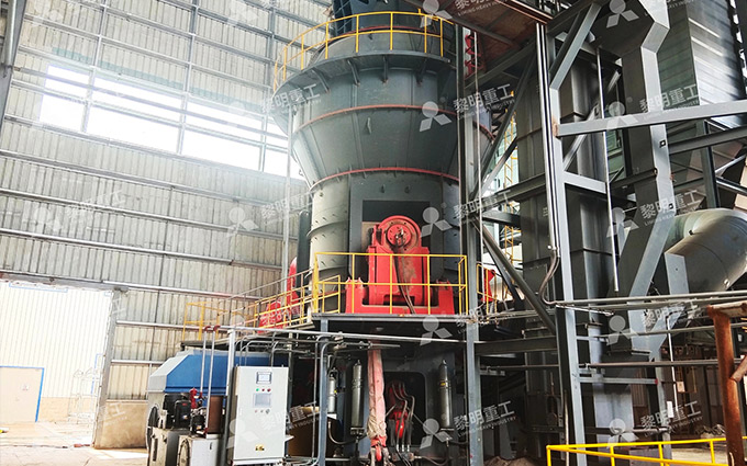
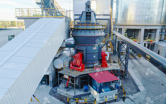
The core of the plant is the LM Vertical Slag Mill. Rather than separating the drying, grinding, and classification stages into multiple major machines, this system performs them inside one mill circuit. The process uses a material-bed grinding principle: slag is fed onto a rotating table, distributed outward by centrifugal force, and compressed under hydraulically loaded rollers.
Hot gas enters the lower mill section and rises through the grinding zone. The gas removes moisture from the slag and carries fine particles toward the upper classifier. Fine powder passes through the classifier and proceeds to collection; coarse material is rejected and returns to the grinding table for further size reduction.
Feed slag → grinding table → roller compression → hot-air drying → classifier → fine GGBS to collector / coarse material back to table
The LM Vertical Slag Mill integrates drying, grinding, powder selection, and conveying, which makes it suitable for industrial residue processing and supports a compact plant arrangement.
Grinding Mill Package
| Equipment | Function in the Plant | Design Consideration |
|---|---|---|
| LM Vertical Slag Mill | Dries, grinds, classifies, and internally circulates slag particles | Select according to output, target fineness, slag moisture, and grindability |
| Mill feed system | Delivers a controlled quantity of prepared slag | Must prevent feed surges and accommodate the bulk behavior of wet slag |
| Hot-gas generator or waste-heat connection | Supplies drying energy to the mill | Size for maximum expected moisture, not only average feed moisture |
| Mill fan | Creates airflow for drying and powder transport | Must match pressure losses across the mill, ducts, and collector |
| Dynamic classifier | Separates fine powder from coarse material | Controls particle-size distribution and product fineness |
| Hydraulic system | Applies and regulates grinding force to the rollers | Supports stable material-bed grinding and facilitates maintenance access |
| Electrical and automation system | Monitors and adjusts mill operation | Should integrate feed rate, temperature, airflow, vibration, pressure, and separator control |
Powder Collection and Storage
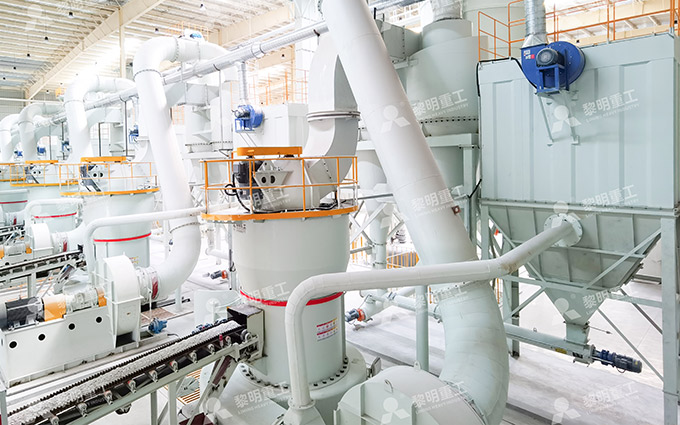
Fine GGBS leaves the mill with the process gas and is recovered in a high-efficiency dust collector, commonly a bag filter. The recovered powder is conveyed through air slides, screw conveyors, bucket elevators, or other enclosed equipment to finished-product silos. Process gas is cleaned before it exits through the stack or returns to the system, depending on the plant design.
Finished-product silos should be designed to maintain dry, consistent powder and support the required dispatch capacity. Important features include level measurement, aeration, dust collection at the silo top, flow-control devices, weighing equipment, and access for maintenance and inspection.
The storage and dispatch area may include:
Finished GGBS silos with loading and high-level protection systems
Air slides or enclosed conveyors for powder transfer
Bulk tanker loading stations with weighing control
Bagging machines for markets that require packaged material
Big-bag filling systems for project-based or export-oriented deliveries
Dedicated dust filters at loading and packing points
The general equipment chain used in slag grinding facilities commonly includes material handling, feeding, grinding and classification, storage, and packing or loading systems.
Plant Layout Principles
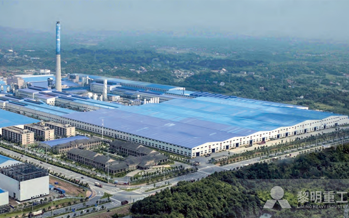
A practical GGBS grinding-plant layout should follow the direction of material flow and minimize unnecessary handling. The goal is to avoid repeated conveying, sharp turns, excessive vertical lifts, long ducts, and congestion around equipment that requires regular maintenance.
Recommended Functional Zones
| Plant Zone | Main Equipment | Layout Priority |
|---|---|---|
| Receiving zone | Truck tippler, unloading hopper, conveyors, dust collector | Provide safe vehicle movement and direct access to raw-slag storage |
| Raw-slag storage zone | Covered yard, storage shed, stacker, reclaimer, reclaim conveyor | Allow enough buffer capacity while limiting rain exposure and rehandling |
| Preparation zone | Screens, magnets, hoppers, weigh feeder, transfer conveyors | Place directly upstream of the mill feed point to reduce feed fluctuations |
| Grinding tower | LM Vertical Slag Mill, feed equipment, classifier, ducts, fan connections | Provide sufficient building height, structural support, crane access, and maintenance clearance |
| Gas-treatment zone | Bag filter, process fan, exhaust stack, hot-gas system | Keep ducts short and accessible; allow space for filter maintenance and fan servicing |
| Finished-product zone | GGBS silos, air slides, loading station, bagging line | Locate close to the plant exit and dispatch route to reduce internal transport |
| Utility and control zone | Electrical room, control room, compressor, workshop, laboratory | Provide safe access without interfering with material and vehicle traffic |
In a vertical configuration, the mill and classifier naturally occupy a central tower structure, while the collector, fan, and finished-product conveying system are arranged adjacent to the tower. This layout supports short powder-transfer routes and allows gravity to assist part of the material flow.
Layout Decisions That Affect Performance
The arrangement of auxiliary equipment has a direct impact on mill stability and operating cost. Several design choices deserve early attention:
Raw-slag storage capacity: A larger buffer can protect production from supply disruptions, but storage should remain practical to reclaim and should not expose slag unnecessarily to rain.
Heat-source location: Position the hot-gas generator or waste-heat connection to keep ducts short and reduce heat loss and pressure drop.
Mill maintenance access: Reserve lifting and removal space for grinding rollers, table liners, classifier parts, and drive-system components.
Dust-control coverage: Enclose receiving, conveying, feeding, collection, storage, and loading points to control powder loss and maintain a clean site.
Finished-product logistics: Size silo capacity and loading facilities according to daily dispatch volume, tanker turnaround, and any bagging demand.
Future expansion: Leave space for added storage, a second loading lane, a larger collector, or a parallel grinding line where long-term demand supports it.
For example, a plant located next to a steelworks may use a direct enclosed conveyor from the granulation area to covered storage. A plant receiving slag by truck may need a larger receiving hopper, a truck circulation area, dust-controlled unloading, and more storage capacity to compensate for delivery variations. The grinding technology may be the same, but the supporting layout changes substantially.
Automation, Quality Control, and Utilities
A modern GGBS plant requires process control that connects the mill with the preparation, drying, collection, and storage sections. The control system should track feed rate, feed moisture, hot-gas temperature, mill outlet temperature, grinding pressure, separator speed, airflow, differential pressure, vibration, collector performance, and silo levels.
Laboratory and online quality-control routines should verify incoming-slag condition and finished-product properties. Typical checks include moisture, specific surface area, sieve residue, particle-size distribution, chemical composition, and strength-activity performance under the applicable product specification.
Utility planning should cover electrical supply, fuel or waste heat for drying, compressed air, process water where needed, lighting, drainage, fire protection, and communication systems. All utility routes should be considered before finalizing foundations, roads, electrical rooms, and equipment elevations.
Planning a Reliable GGBS Grinding Plant
A reliable GGBS grinding plant is a balanced system rather than a single mill. Raw-slag storage must support the mill, feed preparation must protect it, the hot-gas system must dry the wettest expected material, classification must control fineness, and storage and loading must keep pace with production.
The LM Vertical Slag Mill from Liming Heavy Industry provides the central processing unit for this route by combining wet-slag drying, material-bed grinding, dynamic classification, and pneumatic conveying. With a logical layout around receiving, preparation, grinding, collection, storage, and dispatch, the plant can produce consistent GGBS powder while maintaining efficient material flow and practical maintenance access.