GGBS Grinding Plant
How to Design a GGBS Grinding Plant?
2026-09-10 11:02:25
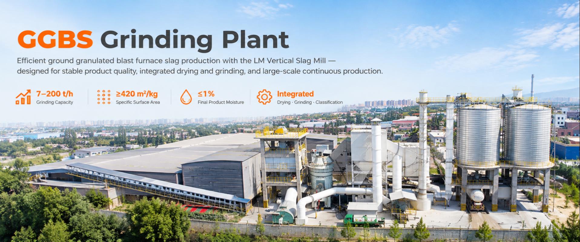
Designing a GGBS grinding plant begins with the actual slag source and the required finished-powder specification. The plant must convert wet granulated blast-furnace slag into a stable, fine, low-moisture product through a balanced system of receiving, storage, preparation, drying, grinding, classification, collection, storage, and dispatch.
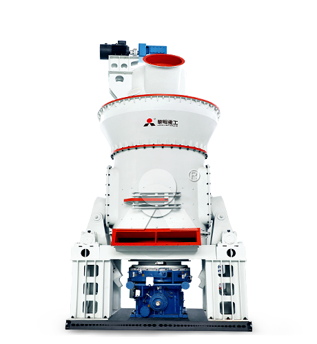
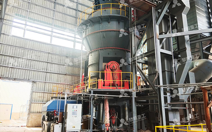
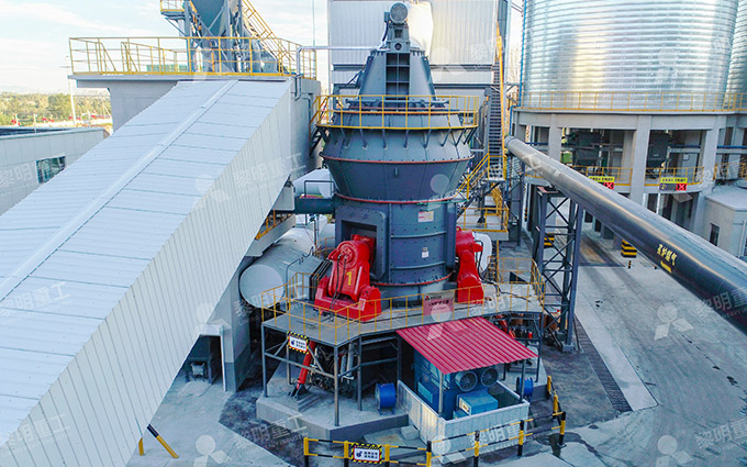
For a dedicated production line, the LM Vertical Slag Mill from Liming Heavy Industry should be the central process unit. It integrates hot-gas drying, material-bed grinding, dynamic classification, and pneumatic powder conveying, enabling a compact and coordinated route from wet slag to finished GGBS.
Define the Design Basis First
A grinding plant should not be sized from annual output alone. The engineering basis needs to state what the plant must produce, what material it will receive, and under which operating conditions it must remain stable.
| Design Input | Questions to Answer | Why It Controls the Design |
|---|---|---|
| Production target | How many tonnes of GGBS are required per hour, per day, and per year? | Determines mill size, silo capacity, dispatch equipment, and utility demand |
| Operating schedule | How many shifts, operating days, and maintenance days are planned each year? | Converts annual demand into realistic required hourly capacity |
| Product grade | What Blaine value, sieve residue, particle-size distribution, moisture limit, and activity level are required? | Determines grinding intensity, classifier setting, laboratory equipment, and mill operating margin |
| Slag source | What are the chemical composition, glass content, grindability, and variability of the granulated slag? | Influences achievable fineness, grinding power, wear rate, and product performance |
| Feed moisture | What are the average, maximum, seasonal, and storage-related moisture levels? | Sets the capacity of the hot-gas system and may limit throughput |
| Feed size and contamination | What are the normal granule size, oversize fraction, tramp-metal content, and foreign-material risk? | Determines screening, magnetic separation, conveying, and feed-protection equipment |
| Dispatch method | Will product leave by bulk tanker, bags, big bags, rail, barge, or a combination? | Determines finished-silo volume, loading capacity, packing equipment, and traffic layout |
| Site utilities | What electrical capacity, fuel, waste heat, water, compressed air, and land are available? | Defines the practical process arrangement and total investment scope |
Use representative slag samples from the intended supply source. A laboratory program should evaluate moisture, chemical composition, physical condition, grindability, achievable fineness, and strength activity. If the project expects more than one slag source, test them separately and design the plant for the more difficult condition or establish blending rules before construction.
Calculate Required Mill Capacity
The required hourly capacity should include an operating margin for maintenance, seasonal moisture changes, product-grade changes, and normal process variation. A simple planning calculation is:
Required hourly output=Annual GGBS demand/(Planned annual operating hours×availability factor)
For example, a plant targeting 300,000 tonnes of finished GGBS per year and planning 7,200 scheduled operating hours at 90% availability requires:
300,000/(7,200×0.90)=46.3 t/h
The mill should then be selected based on its verified capacity at the specified final fineness and maximum design moisture—not on a nominal capacity stated for a drier feed or a coarser product. A line designed for 46 t/h dry slag may not achieve 46 t/h when the incoming material is wetter and the customer requires a higher Blaine target.
Build the Process Around the LM Vertical Slag Mill
The LM Vertical Slag Mill should sit at the center of the process because it combines the main transformation stages: drying wet granulated slag, grinding it under roller pressure, separating fine powder from coarse particles, and conveying qualified powder to the collection system.
The recommended material flow is:
Slag receiving → covered storage → reclaiming → screening and metal removal → weighing and feeding → hot-gas drying and LM vertical grinding → dynamic classification → dust collection → finished GGBS silos → bulk loading or packing
GGBS production commonly includes granulation or quenching, dewatering and/or drying, crushing or preparation, fine grinding, and storage. A plant built around this sequence can manage the material from wet raw slag through to dry finished powder.
Raw-Slag Receiving and Storage
Plan the receiving area around actual logistics. An adjacent steelworks may supply slag by enclosed conveyor, while an independent plant may receive it by truck, rail, or barge. The storage design should provide enough buffer capacity to protect grinding operation from short supply interruptions.
Covered storage is strongly recommended where moisture variation is significant. Rainwater raises the drying load, increases the risk of material buildup, and can reduce the available mill output. Effective yard drainage, controlled stacking, and reclaiming equipment help maintain a more consistent feed condition.
Preparation and Metered Feeding
Before entering the mill, slag should pass through screening and metal-removal equipment. A typical preparation arrangement includes a receiving hopper, belt conveyors, screen, suspended magnet, metal detector, buffer bin, and weigh feeder.
The weigh feeder is particularly important. The LM Vertical Slag Mill needs a stable feed to maintain a consistent grinding bed. Sudden feed surges can increase vibration and differential pressure; insufficient feed can destabilize roller-table contact and reduce grinding efficiency.
Drying System
Because granulated slag is normally water-quenched, the grinding plant must include a properly sized hot-gas source. The heat source may be a hot-gas generator, a suitable waste-heat connection, or another controlled thermal system. The final choice depends on fuel availability, gas temperature, gas cleanliness, reliability, and local environmental requirements.
Design the drying system for the maximum expected moisture condition. Do not base it only on the annual average. The thermal balance should account for slag moisture, feed rate, ambient conditions, hot-gas temperature, air leakage, duct heat loss, required mill outlet temperature, and desired finished-powder moisture.
Finished-product moisture needs to remain within the applicable product specification, and producers should monitor it as part of normal quality control.
Grinding and Classification
In the LM Vertical Slag Mill, material enters the center of a rotating grinding table and is distributed beneath grinding rollers. Hydraulic pressure compresses the slag bed, reducing the granules to fine powder. Hot gas rises through the mill, removes moisture, and transports fine particles toward the internal classifier.
The classifier rejects coarse particles back to the grinding table and allows qualified GGBS to leave with the process gas. This internal loop provides the fineness control required for grades such as S95 or S105. The mill selection should include adequate capacity at the required Blaine value, residue limit, and particle-size distribution—not only at a general powder specification.
Select the Complete Equipment Package
| Plant Section | Key Equipment | Purpose |
|---|---|---|
| Receiving | Truck tippler or unloading hopper, conveyors, transfer-point filter | Accepts raw slag safely and controls dust during unloading |
| Raw storage | Covered yard or shed, stacker, reclaimer, reclaim conveyor | Buffers supply variation and limits moisture pickup |
| Preparation | Screen, magnetic separator, metal detector, buffer bin | Protects the mill from oversize and ferrous contamination |
| Metering | Weigh feeder and feed conveyor | Maintains stable mill loading and accurate production accounting |
| Drying | Hot-gas generator or waste-heat system, ducts, dampers, instrumentation | Evaporates feed moisture and supports pneumatic transport |
| Grinding | LM Vertical Slag Mill, hydraulic system, drive, internal classifier | Performs drying, grinding, coarse return, and fineness separation |
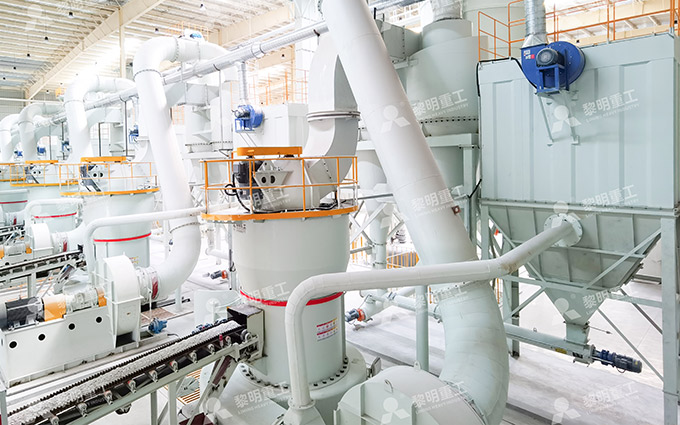
| Gas treatment | Bag filter, process fan, ducts, stack | Collects fine GGBS and cleans the process gas |
| Product handling | Air slides, screw conveyors, bucket elevator, finished-product silos | Transfers and stores dry GGBS without contamination or moisture pickup |
| Dispatch | Bulk loading station, weighbridge, bagging machine, big-bag filler | Supplies the product in the required commercial format |
| Quality and control | Laboratory, sampling equipment, control room, analyzers, automation system | Verifies product quality and maintains stable operation |
Plan the Layout and Building
Arrange the plant along the natural direction of material flow. Raw slag should move from receiving to storage, preparation, and the mill with as few transfer points as possible. Finished GGBS should move directly from the collector to silos and dispatch facilities.
A practical layout usually separates the site into six functional zones:
Receiving zone: Vehicle unloading, traffic circulation, raw-material sampling, and dust-controlled transfer.
Raw-slag storage zone: Covered storage, drainage, stacking, reclaiming, and a buffer sized for delivery interruptions.
Mill-feed zone: Screening, magnetic separation, buffer bin, weigh feeder, and short conveyor route to the LM Vertical Slag Mill.
Grinding tower: Mill, drive, classifier, feed equipment, hot-gas ducts, maintenance platforms, and lifting arrangements.
Gas-treatment zone: Bag filter, process fan, ducts, stack, and access space for filter-bag replacement and fan maintenance.
Finished-product zone: Product silos, loading lanes, bagging or big-bag equipment, weighbridge, and dispatch traffic route.
Provide adequate structural height for the grinding tower and enough crane access for roller, table-liner, classifier, and drive maintenance. Keep hot-gas ducts short and insulated. Locate the dust collector and fan to avoid unnecessarily long ductwork, which can increase pressure drop and fan power.
Design for Stable Operation
A GGBS plant should include instrumentation that allows operators to control drying, grinding, and classification as one process. The main control variables are feed rate, feed moisture, hot-gas temperature, mill inlet and outlet temperature, airflow, grinding pressure, separator speed, mill differential pressure, vibration, motor power, bag-filter pressure drop, and finished-silo level.
Data-driven grinding control has been studied specifically for GGBS production, with quality consistency and reduced mill vibration identified as key control targets.
The laboratory should test raw slag and finished GGBS according to the selected standard and customer specification. Typical tests include:
Raw-slag moisture, chemical composition, glass content, and physical condition
Finished-powder moisture, Blaine fineness, and sieve residue
Particle-size distribution when a detailed powder profile is required
Strength activity index and other performance checks
Routine sampling, retention, traceability, and product-release records
Quality-control testing should follow a documented producer or supplier quality-management plan.
Design for Energy and Maintenance
Energy performance depends on the entire plant, not only on the mill drive. The design should reduce unnecessary drying heat, false-air leakage, fan pressure loss, excessive conveying distance, and avoidable overgrinding.
Use covered storage and drainage to limit avoidable moisture addition.
Evaluate suitable waste-heat recovery before installing a dedicated fuel-fired heat source.
Insulate hot ducts and keep them short to reduce thermal losses.
Specify efficient fans and consider variable-speed control for suitable loads.
Provide inspection doors, access platforms, lifting beams, and maintenance clearance during initial civil design.
Install reliable magnetic separation to reduce wear and avoid damage from metallic contaminants.
Plan critical spare parts for grinding rollers, table liners, classifier components, hydraulic elements, fans, filters, and feeder drives.
Leave space for future silo capacity, a second loading position, or an additional grinding line if market growth is expected.
Final Design Checklist
Before finalizing the engineering package, confirm that the design answers the following questions:
Can the plant achieve the required output at maximum feed moisture and target fineness?
Has the mill been selected using actual slag test data rather than nominal capacity alone?
Does the hot-gas system have enough thermal capacity for the wettest expected feed?
Are screening, magnetic separation, and weighing systems adequate to protect and stabilize the mill?
Is raw-slag storage sufficient to manage supply disruption and seasonal moisture variation?
Are the dust collection, fan, and duct systems sized for stable gas flow and practical maintenance?
Do finished-product silos and loading facilities match the planned dispatch volume?
Does the layout provide safe access for maintenance, sampling, vehicle movement, and emergency response?
Are product testing, traceability, and release procedures defined before commissioning?
Is there a practical route for future capacity expansion?
A successful GGBS grinding plant is a complete process system built around consistent feed, adequate drying capacity, controlled fine grinding, reliable powder collection, and efficient dispatch. By centering the line on an LM Vertical Slag Mill from Liming Heavy Industry and designing each supporting section around the real slag condition and product specification, producers can create a stable route from wet granulated slag to high-quality finished GGBS.