Cement Clinker Grinding Plant
Cement Grinding Plant Layout
2026-09-10 08:15:48
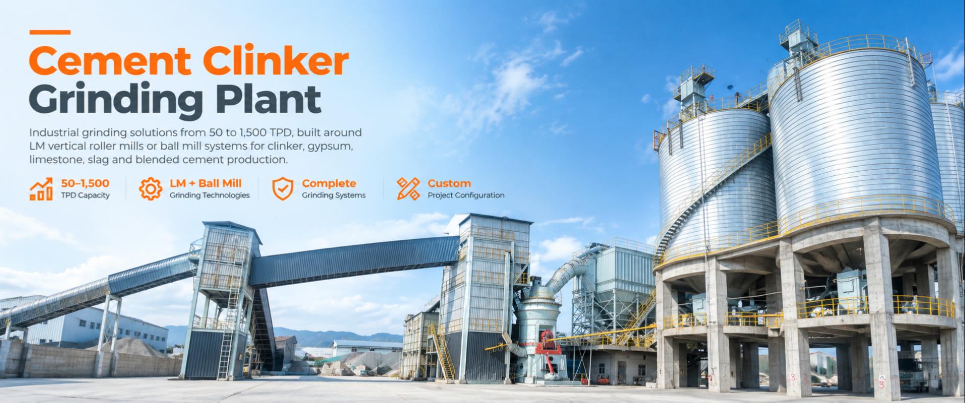
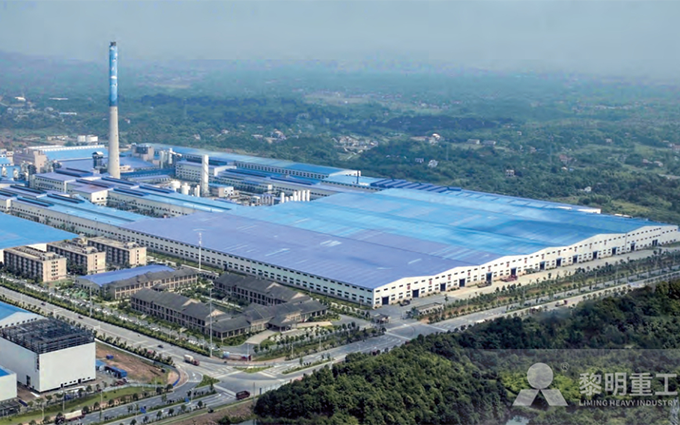
A cement grinding plant layout organizes clinker receiving, material storage, dosing, grinding, classification, dust collection, finished-cement storage, packing, and dispatch into one efficient production flow. The layout must support stable cement output, safe maintenance access, reliable material handling, environmental control, and future plant expansion.
Liming Heavy Industry provides cement grinding plant solutions built around the LM Vertical Roller Mill and cement ball mill. The final layout depends on required production capacity, cement type, clinker properties, gypsum and additive ratios, target fineness, site dimensions, existing infrastructure, transport method, electricity supply, packing requirement, and future development plans.
Basic Layout Principle
A well-designed cement grinding plant follows the material flow from receiving to dispatch. Clinker, gypsum, limestone, slag, fly ash, and other suitable additives should enter the site, move through separate storage and dosing systems, pass through the grinding circuit, and finally reach cement silos, packing machines, and bulk loading stations.
The layout should minimize unnecessary conveying distance, material transfer points, elevation changes, and cross-traffic between raw materials and finished products. It should also provide enough space for maintenance, lifting, inspection, equipment replacement, dust-control systems, electrical rooms, control rooms, truck circulation, and future capacity expansion.
For stand-alone cement grinding stations, the plant is often located near the cement market, a port, railway connection, or other reliable clinker transport route. This can reduce the distance required to deliver finished cement to customers while allowing clinker to be received from an integrated clinker production plant. Site selection and layout should therefore consider both raw-material supply and finished-product distribution. [66]
Typical Cement Grinding Plant Areas
| Plant Area | Main Equipment | Layout Purpose |
|---|---|---|
| Material receiving area | Truck unloading station, railway unloading system, port unloading equipment, hoppers, conveyors | Receives clinker, gypsum, limestone, slag, fly ash, and other materials safely and efficiently |
| Clinker storage area | Clinker silo, clinker hall, dome, covered stockpile, reclaiming equipment | Maintains clinker inventory and provides stable feed to the grinding plant |
| Gypsum and additive storage | Covered shed, storage bins, silos, hoppers, conveyors, crushers where required | Stores each cement component separately and prevents contamination |
| Dosing and feeding area | Belt weigh feeders, screw feeders, bins, hoppers, belt conveyors, bucket elevators | Measures clinker, gypsum, and additives accurately before grinding |
| Grinding building | LM Vertical Roller Mill or cement ball mill, mill drive, separator, process fans, ducts | Performs clinker grinding and fineness control |
| Dust collection area | Bag filters, dust conveyors, process fans, ducts, stacks, air locks | Recovers fine cement and controls dust emissions |
| Finished cement storage | Cement silos, aeration systems, level indicators, discharge gates, silo filters | Stores finished cement before packing or bulk dispatch |
| Packing and dispatch area | Rotary packing machines, bag conveyors, truck loading stations, bulk loading spouts | Loads bagged or bulk cement for customer delivery |
| Utility and control area | Substation, MCC room, PLC room, central control room, compressor station, workshop | Supports power distribution, automation, maintenance, and plant management |
Typical Material Flow
The material flow should be clear, direct, and continuous. A practical cement grinding plant layout generally follows the sequence below:
Clinker arrives by truck, rail, ship, or conveyor and enters the clinker receiving station.
Clinker is stored in a silo, dome, clinker hall, or covered storage area.
Gypsum and mineral additives are delivered to separate storage areas.
Clinker, gypsum, and additives are discharged through hoppers and measured by weigh feeders.
The proportioned material mix is conveyed to the LM Vertical Roller Mill or cement ball mill.
Ground material is classified to separate fine cement from coarse particles.
Fine cement is recovered by bag filters and conveyed to finished-cement silos.
Coarse material is returned to the grinding system for additional processing where required.
Finished cement is dispatched through bag packing machines or bulk loading equipment.
A typical grinding-station arrangement includes clinker storage, gypsum storage, fly ash and slag storage, cement grinding equipment, finished-cement silos, packing facilities, and truck loading areas. Ground material collected by bag filters is commonly transferred to cement silos through air slides and bucket elevators. [65]
LM Vertical Roller Mill Layout
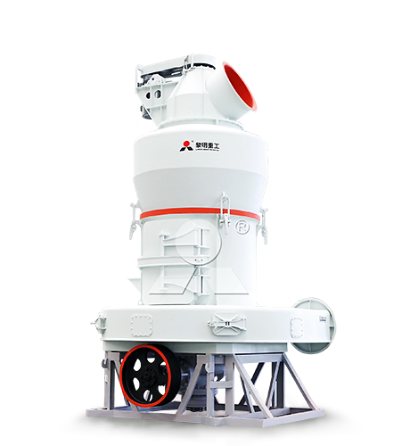
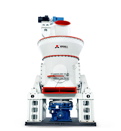
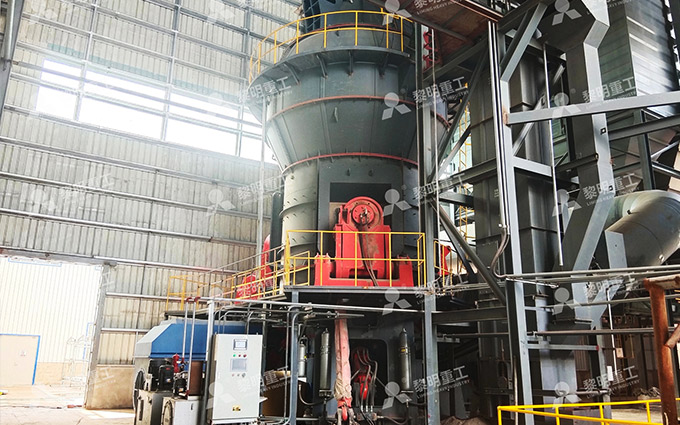
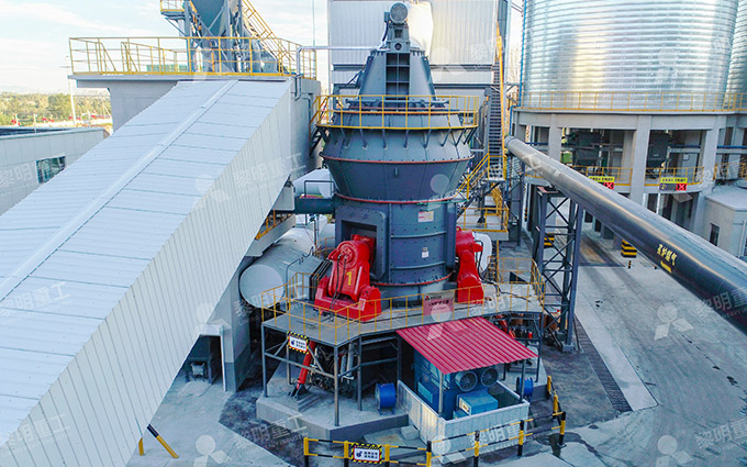
An LM Vertical Roller Mill uses a compact vertical arrangement in which grinding and dynamic classification are integrated into one main process system. Clinker, gypsum, and additives are fed to the mill, ground on a rotating table between grinding rollers, and lifted by process air to an internal dynamic classifier.
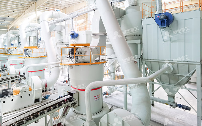
Fine cement leaves the mill with the gas stream and is collected by a bag filter. Coarse material is rejected by the classifier and returns internally to the grinding table for further grinding. This arrangement reduces the need for a separate external separator-and-return circuit used in conventional ball mill systems.
The LM Vertical Roller Mill layout normally includes a material feeding floor, mill body, hydraulic system, main drive, gearbox, separator, process fan, bag filter, ducts, product conveying equipment, electrical controls, and a maintenance area. The mill building must provide adequate vertical clearance for installation, inspection, roller maintenance, classifier service, and lifting operations.
| LM Vertical Roller Mill Layout Component | Typical Position in the Plant | Main Design Requirement |
|---|---|---|
| Feed bins and weigh feeders | Upstream of the mill feed point | Provide stable and accurately proportioned clinker, gypsum, and additive feed |
| LM Vertical Roller Mill | Central grinding building | Provide sufficient building height, structural support, vibration consideration, and service access |
| Dynamic classifier | Integrated in the upper mill structure | Allow access for inspection, adjustment, and maintenance |
| Process fan and ducts | Near the mill outlet and bag filter system | Minimize duct length and pressure loss while allowing safe maintenance access |
| Bag filter | Downstream of the mill gas outlet | Allow access for filter-bag replacement, dust discharge, and fan maintenance |
| Finished-product conveying | Between bag filter and cement silos | Use air slides, bucket elevators, screw conveyors, or other suitable equipment |
| Maintenance area | Adjacent to or inside the grinding building | Provide lifting equipment, service platforms, access routes, and spare-parts handling space |
An LM Vertical Roller Mill can also support simultaneous drying and grinding when suitable hot gas is available. If the project uses moist slag, limestone, gypsum, or other additives, the layout may require hot-gas ducts, a gas generator or kiln-gas connection, dampers, temperature-control equipment, and suitable insulation.
Cement Ball Mill Layout
A cement ball mill layout is normally based on a conventional horizontal closed-circuit grinding system. The main mill is installed on a reinforced concrete foundation, with sufficient surrounding clearance for the drive system, lubrication equipment, grinding-media charging, liner replacement, diaphragm maintenance, and mill inspection.
Clinker, gypsum, and additives are fed into the ball mill. After grinding, the mill discharge is conveyed to a separate high-efficiency separator. Fine cement is collected by the bag filter and transferred to finished-cement silos. Coarse separator reject is returned to the mill through bucket elevators, conveyors, air slides, or another circulation system.
| Ball Mill Layout Component | Typical Position in the Plant | Main Design Requirement |
|---|---|---|
| Feed bins and weigh feeders | Upstream of ball mill inlet | Ensure stable clinker, gypsum, and additive proportioning |
| Cement ball mill | Central horizontal grinding area | Provide adequate foundation, mill access, drive-space clearance, and maintenance room |
| Mill drive system | At the mill end or side according to configuration | Allow access to motor, gearbox, pinion, girth gear, coupling, and lubrication system |
| Separator | Downstream of mill discharge | Provide vertical space, duct connection, inspection platforms, and return-material connection |
| Bucket elevator | Between mill discharge, separator, and return loop | Provide vertical lift capacity and safe access for bucket, belt, and drive maintenance |
| Bag filter and process fan | Connected to separator and grinding-circuit gas flow | Provide dust collection, pressure control, fine-product recovery, and maintenance access |
| Reject-return system | Between separator reject outlet and mill feed | Handle circulating load reliably without blockage or excessive transfer points |
| Finished-product conveying | Between separator or bag filter and cement silos | Match the grinding capacity and provide dust-tight transfer |
A ball mill layout usually requires more horizontal space than an LM Vertical Roller Mill system because the mill, separator, elevator, and external circulation loop are arranged as separate process units. However, ball mills remain a practical option for projects with existing mill foundations, buildings, separators, conveyors, and experienced maintenance teams.
Layout Comparison
| Layout Factor | LM Vertical Roller Mill | Cement Ball Mill |
|---|---|---|
| Main arrangement | Vertical and compact, with integrated grinding and classification | Horizontal and conventional, with separate grinding and classification equipment |
| Building height | Usually requires greater vertical clearance for mill body, classifier, ducts, and service access | Usually requires more horizontal length for mill, separator, elevator, and return circuit |
| External separator | Normally not required because classification is integrated | Normally required for closed-circuit cement grinding |
| Return-material circuit | Coarse material generally returns internally to the grinding table | Requires external reject return through elevator, conveyor, or air-slide system |
| Grinding media handling | No large steel-ball charging system required for the main grinding process | Requires space for grinding-media storage, charging, and handling |
| Maintenance planning | Requires roller, grinding-table, hydraulic, classifier, and gearbox maintenance access | Requires liner, diaphragm, grinding-media, bearing, gear, drive, and separator maintenance access |
| Suitable layout condition | New projects requiring compact process integration and limited land use | Existing plants with compatible ball mill foundations and conventional grinding infrastructure |
Vertical roller mill systems can reduce horizontal plant footprint because grinding and classification are combined. Ball mill systems commonly require separate classification and return-circulation equipment. The final choice should be made through a complete comparison of equipment cost, civil works, power demand, maintenance requirement, available site dimensions, existing equipment, and operating objectives. [66][67]
Storage Layout
Storage layout should provide sufficient inventory without creating unnecessary material transfer or traffic congestion. Clinker storage is typically placed close to the receiving area and upstream of the grinding building. This reduces conveyor distance and helps maintain a stable clinker feed.
Gypsum and other additives should be stored near the dosing system but separated from clinker and from each other. Dry additives such as fly ash may be stored in silos, while materials such as gypsum, limestone, and slag may require covered sheds, enclosed bins, or specialized storage depending on moisture, flowability, and delivery method.
Finished-cement silos should be located downstream of the grinding circuit and close to the packing and bulk loading area. This allows short, efficient product-conveying routes and supports fast dispatch. Plants producing multiple cement grades should provide separate silos or suitable silo-management arrangements to avoid cross-contamination.
Packing and Dispatch Layout
The packing plant should be positioned close to finished-cement silos and truck circulation routes. Cement can be discharged from silos to rotary packing machines, bag conveyors, loading stations, and warehouses. The layout should separate incoming raw-material traffic from outgoing bagged-cement and bulk-cement traffic where possible.
Bulk loading stations should provide enough space for trucks to enter, position under loading spouts, load safely, and exit without interfering with packing operations. Loading systems should include dust-control equipment, vehicle access lanes, traffic signs, weighing facilities where required, and sufficient turning radius for the largest expected vehicles.
For high-capacity plants, the packing and dispatch system should be designed with enough capacity to prevent finished-cement silos from becoming full. If the silos cannot receive more cement, the grinding mill may need to reduce output or stop, even if all grinding equipment is operating normally.
Utility, Control, and Maintenance Areas
Electrical rooms, substations, motor control centers, PLC cabinets, central control rooms, compressor stations, workshops, laboratories, spare-parts warehouses, and maintenance areas should be integrated into the overall layout. These facilities should be close enough to the main equipment for efficient operation but protected from excessive dust, vibration, noise, and heat.
The central control room should have reliable communication with the grinding circuit, packing plant, material receiving area, laboratory, and dispatch area. The electrical system should be located to reduce cable length while maintaining safe access and fire-protection requirements.
Maintenance access must be considered during the first layout stage. The design should provide service platforms, walkways, lifting beams, cranes, forklift routes, roller-removal space for LM Vertical Roller Mills, liner-handling space for ball mills, and access to bag filters, fans, gearboxes, conveyors, elevators, and electrical equipment.
Dust Control and Environmental Layout
Dust-control equipment should be located as close as practical to major dust-generation points. These points include clinker unloading, gypsum crushing, material transfer stations, mill feed, grinding equipment, separators, bucket elevators, cement silos, packing machines, and bulk loading stations.
Bag filters, ducts, fans, and dust-return conveyors must be integrated into the layout so that dust is collected efficiently and recovered material can be returned to the process. Enclosed conveyors, sealed transfer chutes, properly designed hoppers, and negative-pressure ventilation help reduce dust leakage.
Noise control, stormwater drainage, road cleaning, covered material storage, and green-buffer zones may also be considered according to local site conditions and environmental requirements.
Future Expansion Planning
Future expansion should be considered before construction begins. A plant may initially install one grinding line but later need additional mill capacity, larger clinker storage, more cement silos, a second packing line, or expanded bulk loading facilities.
Practical expansion planning can include reserving land beside the grinding building, sizing roads and utility corridors for future use, allowing space for additional silos, providing electrical capacity margin, and arranging conveyors so they can be extended without major reconstruction.
For an integrated cement project, future expansion planning should also consider rotary kiln capacity, clinker cooling capacity, clinker storage, raw-material handling, cement grinding output, finished-cement storage, and dispatch capability. Liming Heavy Industry can provide rotary kiln and calcining kiln solutions for projects that require clinker production as well as cement grinding.
Conclusion
A cement grinding plant layout should create a direct, reliable flow from clinker receiving to finished-cement dispatch. The layout must coordinate storage, dosing, grinding, classification, dust collection, silos, packing, bulk loading, electrical systems, automation, maintenance access, and environmental control.
Liming Heavy Industry provides LM Vertical Roller Mill solutions for compact integrated grinding and classification layouts, as well as cement ball mill solutions for conventional closed-circuit grinding systems. The LM Vertical Roller Mill is suitable for projects seeking a compact vertical arrangement, while a cement ball mill can be a practical choice for sites with compatible existing foundations, buildings, and grinding infrastructure.
For complete cement projects, Liming Heavy Industry can also supply rotary kilns, calcining kilns, and supporting equipment for clinker production, cement grinding, finished-cement storage, packing, and dispatch.