FGD Limestone Grinding Plant
FGD Limestone Powder Storage and Conveying System Design
2026-09-19 10:36:14
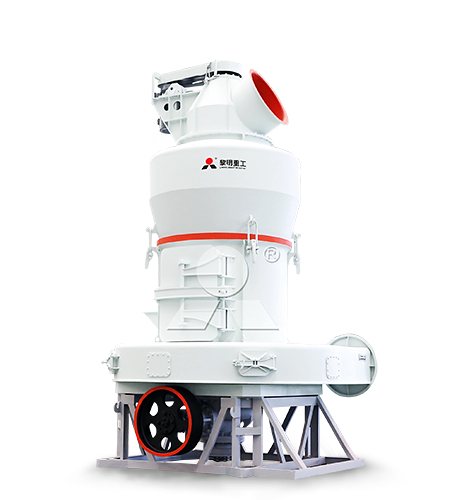
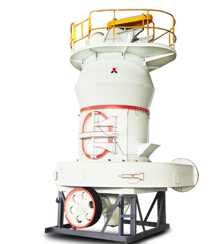
We are Liming Heavy Industry, a manufacturer of various types of industrial crushers, such as Raymond Mill, Trapezoidal Mill, Vertical Mill, Ultrafine Mill, Ball Mill, etc.
Our mills can process the following minerals:
limestone, quicklime, kaolin, talc, barite, bentonite, calcium carbonate, dolomite, coal, gypsum, clay, carbon black, slag, cement raw materials, cement clinker, etc.
If you need a mill to process stone or minerals into powder, please feel free to contact me (WhatsApp: +8615333807511). Thank you.
A well-designed limestone powder storage and conveying system keeps the wet FGD absorber supplied with stable reagent even when grinding output changes or the mill is temporarily unavailable. The system must protect powder quality, prevent moisture absorption and bridging, limit dust release, maintain accurate dosing, and provide enough inventory for the plant’s required operating reserve.
The process normally follows this route: grinding mill → dust collector → powder conveying → finished-powder silo → controlled dosing → slurry preparation tank → slurry storage → FGD absorber. Fine limestone powder is mixed with water in the slurry preparation tank and then pumped to the absorber, where the alkaline slurry reacts with sulfur dioxide.
Design Basis
Storage and conveying equipment should be sized from the actual limestone material balance, not from mill nameplate capacity alone. The key inputs include maximum limestone consumption, grinding-system availability, required storage autonomy, powder bulk density, moisture, particle-size distribution, flowability, plant layout, delivery distance, and the required slurry concentration.
| Design Input | Why It Is Important | Typical Engineering Question |
|---|---|---|
| Maximum limestone demand | Defines the required powder conveying rate, silo discharge rate, dosing rate, and slurry preparation capacity. | How many tonnes per hour are needed at maximum boiler load and maximum sulfur condition? |
| Required operating reserve | Determines the usable storage capacity required during mill maintenance, raw-material interruptions, or reduced grinding output. | Must the silo supply the FGD system for 8, 16, 24, or 48 hours without grinding? |
| Limestone bulk density | Converts required mass storage into silo volume and influences conveying-line loading. | What is the loose and aerated bulk density of the finished powder? |
| Particle-size distribution | Affects powder flow, dust loading, pneumatic conveying behavior, and slurry preparation rate. | Does the product meet the FGD fineness requirement without excessive ultrafines or coarse particles? |
| Moisture and hygroscopic behavior | High moisture can cause caking, arching, wall build-up, and unstable silo discharge. | Will rainy-season limestone or warm humid air affect powder flow? |
| Flowability and cohesion | Defines hopper angle, outlet size, aeration requirement, and feeder selection. | Will the powder discharge by mass flow, or can it form a rathole or bridge? |
| Conveying route | Determines whether mechanical or pneumatic conveying is more practical. | How far, how high, and through how many bends must powder be transported? |
| Operating reliability | Defines the need for parallel equipment, standby blowers, standby feeders, and emergency powder inventory. | Can the FGD unit continue operating if one conveyor, feeder, or pump is out of service? |
Material characterization should be completed before final design. Powder bulk density, particle-size distribution, abrasiveness, moisture, and flowability are fundamental to correctly sizing pipelines, blowers, filters, hopper outlets, and discharge equipment.
Finished Powder Silo
The finished limestone powder silo is the operating buffer between grinding and slurry preparation. It should receive powder continuously or intermittently from the mill while discharging powder smoothly and accurately to the slurry preparation system.
The minimum usable powder inventory can be estimated as:
Usable silo capacity (t) = Maximum limestone consumption (t/h) × Required backup time (h)
For example, if an FGD absorber consumes 12 t/h of limestone powder and the plant requires 24 hours of independent operation during mill maintenance:
Usable powder inventory = 12 t/h × 24 h = 288 t
The physical silo must be larger than this calculated usable inventory because it also needs allowance for high-level operating limits, low-level dead stock, freeboard, powder-density variation, and the hopper volume that may not discharge completely.
| Item | Recommended Design Consideration |
|---|---|
| Silo capacity | Size from maximum consumption and required grinding outage coverage; use usable capacity rather than total geometric volume. |
| Silo geometry | Use a cylindrical body with a conical hopper designed around the measured flow properties of the limestone powder. |
| Hopper outlet | Select outlet diameter and cone angle to prevent bridging, ratholing, and unstable discharge. |
| Wall material | Use suitable low-friction internal surfaces or liners where the powder shows cohesive behavior or wall build-up. |
| Ventilation | Provide a silo-top vent filter or dust collector to separate displaced conveying air from powder during filling. |
| Pressure protection | Install pressure-vacuum relief equipment sized for the filling and discharge air balance. |
| Level measurement | Use continuous level measurement plus independent high-high and low-low level switches. |
| Discharge aids | Use aeration pads, fluidizing cones, bin activators, air cannons, vibrators, or mechanical agitators only after evaluating actual powder flow behavior. |
| Access and maintenance | Provide inspection openings, safe access platforms, ladders, handrails, lighting, and lockout points. |
Fine limestone powder should not be assumed to flow like grain. Silo geometry and flow aids must be based on the powder’s cohesive behavior, wall friction, and moisture sensitivity. A silo designed without material-flow data can experience bridging, rat-holing, segregation, or large variations in feeder load.
Powder Conveying Options
The best conveying method depends on capacity, distance, elevation, layout constraints, material moisture, and required enclosure. A practical FGD plant may use more than one conveying method: mechanical equipment for short vertical or horizontal transfer and pneumatic conveying for enclosed routing from the mill collector to a remote silo.
| Conveying Method | Best Application | Advantages | Key Limitations |
|---|---|---|---|
| Bucket elevator | Vertical transfer from dust collector or screw conveyor to a nearby silo. | High lifting capacity, moderate energy use, and simple integration with dry powder systems. | Requires mechanical maintenance, good sealing, alignment control, and proper inlet feeding. |
| Screw conveyor | Short horizontal transfer below collectors, silos, and feeders. | Compact, controlled discharge, and suitable for dosing or short enclosed movement. | Not ideal for long distances; abrasive powder can wear flights and troughs. |
| Air slide | Short, nearly horizontal transfer of dry, free-flowing limestone powder. | Low mechanical complexity, enclosed transfer, and gentle powder movement. | Requires dry, fluidizable powder and a suitable elevation difference. |
| Dilute-phase pneumatic conveying | Short to medium distance transfer with flexible routing and moderate powder demand. | Fully enclosed pipeline, adaptable routing, multiple receiving points, and reduced external dust. | Higher conveying air volume, increased blower power, and potential wear at bends if velocity is excessive. |
| Dense-phase pneumatic conveying | Long-distance transfer, abrasive limestone, high conveying rates, or applications seeking lower pipe velocity. | Lower conveying velocity can reduce wear and compressed-air use while providing dust-tight transfer. | Requires specialized pressure-vessel equipment, automated sequencing, and more detailed system design. |
Dilute-phase pneumatic conveying is often suitable for fine limestone powder at short to medium distances, while dense-phase systems can be advantageous for longer routes and abrasive material because they operate at lower conveying velocity.
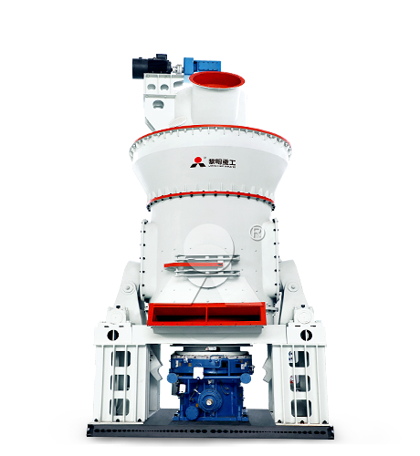
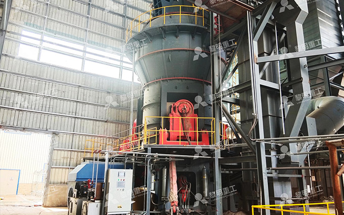
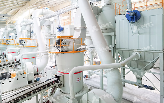
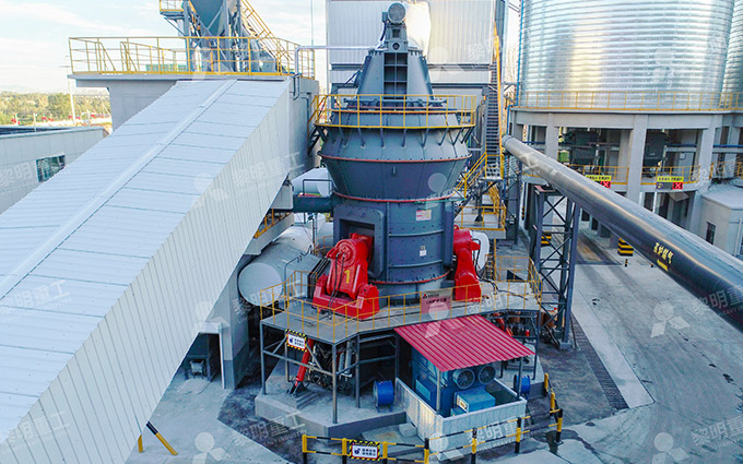
For large FGD limestone powder projects using an LM Vertical Mill, pneumatic conveying or enclosed mechanical conveying can transfer powder from the collection system to one or more finished-product silos. For medium-capacity systems built around an MTW European Mill, a bucket elevator with screw conveyors or a compact pneumatic line is often suitable where the silo is located close to the grinding plant.
Slurry Preparation and Dosing
Powder storage is only useful if limestone can discharge steadily into the slurry preparation system. The discharge arrangement should provide controlled mass flow, accurate dosing, and enough mixing energy to prevent local settling or dry-powder accumulation.
A typical slurry preparation section includes:
Finished-powder silo with controlled discharge outlet.
Rotary valve, screw feeder, loss-in-weight feeder, or gravimetric feeder.
Powder transfer chute or enclosed screw conveyor to the slurry tank.
Process-water supply line with flow meter and control valve.
Slurry preparation tank with a suitably sized agitator.
Density meter or solids-concentration measurement.
Slurry recirculation line where required.
Slurry storage tank with continuous agitation.
Duty-and-standby slurry transfer pumps.
Flow meter, pressure transmitter, isolation valves, and pipeline flushing connections.
For dry limestone powder, the preferred dosing arrangement is normally a controlled feeder rather than uncontrolled gravity discharge. A gravimetric feeder is especially useful where the reagent feed must respond accurately to absorber demand, slurry density, or inlet SO2 load.
The slurry preparation tank should be designed for the required solids concentration and retention time. In one wet limestone FGD reference arrangement, process or recycle water is added during milling to make approximately 70% solids slurry, which is then diluted to about 30% solids in the classification process and stored in a limestone slurry tank before absorber feed.
Controls and Protection
The storage and conveying system should operate as part of the FGD reagent-control loop. It should not allow the mill, silo, feeder, and slurry tank to function as isolated units.
| Control Point | Recommended Instrument or Device | Operating Purpose |
|---|---|---|
| Silo inventory | Radar level transmitter, load cells, high-high level switch, low-low level switch | Prevents overfilling, mill discharge blockage, and low-inventory risk to the FGD absorber. |
| Conveying-line pressure | Pressure transmitter, differential-pressure switch, blower current monitoring | Detects pipeline blockage, air leakage, filter restriction, and abnormal conveying conditions. |
| Powder feed rate | Loss-in-weight feeder, belt scale, screw feeder load cell, gravimetric feeder | Maintains accurate limestone addition to the slurry system. |
| Slurry density | Online density meter, water flow meter, powder-feed signal | Maintains stable slurry concentration and pumpable flow conditions. |
| Slurry tank level | Level transmitter, high-high and low-low alarms | Protects against overflow, pump cavitation, and loss of available reagent inventory. |
| Agitator condition | Motor current monitor, vibration monitor, running feedback | Confirms that solids remain suspended and prevents tank settling. |
| Dust collector condition | Differential-pressure transmitter, hopper level switch, pulse-air pressure monitor | Maintains powder collection efficiency and avoids excessive fan energy use. |
| Slurry delivery | Magnetic flow meter, pump VFD, discharge pressure transmitter, standby pump auto-start | Provides stable reagent supply to the absorber and protects against pump failure. |
Useful interlocks include stopping the incoming powder conveyor when the silo reaches high-high level, stopping the powder feeder when slurry-tank level is too high, preventing powder addition if the agitator is not running, and automatically starting a standby slurry pump if the operating pump trips.
Reliability and Maintenance
The FGD absorber should not lose limestone supply because of one failed feeder, blocked chute, or unavailable slurry pump. The required redundancy depends on plant criticality, but the following practices improve availability:
Provide adequate finished-powder storage for planned mill maintenance and temporary raw-material interruptions.
Use duty-and-standby slurry pumps, with automatic changeover where continuous operation is critical.
Provide two powder discharge paths or a bypass arrangement where a single feeder represents a major production risk.
Use wear-resistant bends, valves, and pipeline sections in abrasive pneumatic conveying service.
Install accessible cleanout ports at long conveying lines, directional changes, and likely accumulation points.
Maintain dry compressed air for aeration pads, pulse filters, and pneumatic conveying systems.
Inspect silo vent filters, pressure-relief devices, feeder seals, and conveying-line supports regularly.
Flush slurry pipelines during extended shutdowns to prevent limestone settlement and hardened deposits.
A wet limestone FGD reference design uses a 30-day bulk limestone pile, a 24-hour limestone day bin, two 100% capacity grinding streams, two 100% capacity classification pumps, and approximately 16 hours of limestone slurry storage before absorber feed. These values are reference examples rather than universal requirements; the right reserve depends on supply reliability, mill configuration, maintenance philosophy, and the consequences of an FGD interruption.
A successful FGD limestone powder storage and conveying system combines adequate inventory, controlled mass flow, sealed transfer, accurate powder dosing, reliable slurry preparation, and redundant critical equipment. When correctly matched to an LM Vertical Mill for high-capacity projects or an MTW European Mill for medium-capacity projects, it provides a stable bridge between limestone grinding and continuous wet FGD operation.